Understanding Pump Curves
A pump curve is a graphical representation of a pump’s hydraulic performance, showing the relationship between the flow rate (typically on the horizontal axis) and the total developed head (vertical axis) at a given impeller diameter and rotational speed (RPM).
What a Pump Curve Shows
At zero flow, the pump develops its maximum head, known as the shut-off head, which appears at the far left of the graph (see figure below). As flow increases, the head that the pump can generate decreases. The curve typically ends at the maximum flow rate—the far right end of the graph—beyond which the pump can no longer move fluid effectively. This shape reflects the fundamental performance of centrifugal pumps.
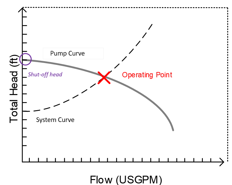
(Note: Shut-off head is located on the far left; the red X indicates the operating point where the pump curve intersects the system curve.)
Best Efficiency Point (BEP)
The efficiency of a pump varies depending on where it operates along its curve. The Best Efficiency Point (BEP) is where the pump achieves its highest efficiency with the least vibration and wear. While not shown in the figure above, the BEP typically lies somewhere near the center of the performance curve and should be used as a guide when selecting a pump. Operating near the BEP reduces energy consumption and extends equipment life.
System Curve and Operating Point
The operating point of a pump is defined by the intersection between the pump curve and the system curve, which represents the total head required by the system at various flow rates (including static and frictional components). This point is marked by a red “X” in the figure above.
If the operating point lies far from the BEP, it may result in poor hydraulic performance, cavitation, noise, or premature mechanical wear. Adjustments such as trimming the impeller or modifying the system can help shift the operating point toward the BEP.
Pump Curve Shape and Stability
The shape of the pump curve indicates how stable the pump is under varying system conditions. A steep curve means the flow changes only slightly with variations in head, which is generally stable. In contrast, a flat section on the curve suggests that even small changes in head can result in large changes in flow, making operation unpredictable. This is undesirable in systems that require tight flow control.
Series and Parallel Pumping
To meet more demanding system requirements, pumps can be configured:
-
In series: Both pumps handle the same flow, but the total head increases (useful when high pressure is needed).
-
In parallel: Flow is split between pumps, but the total flow rate increases while maintaining similar head (useful in high-flow or redundant systems).
Each configuration should be carefully analyzed using combined pump curves to ensure proper system performance.
Summary
Pump sizing is about more than just matching flow and pressure. It involves selecting a pump that operates efficiently and reliably within its design envelope. By understanding and correctly interpreting pump curves—including head, flow, efficiency, and system interaction—engineers can avoid costly mistakes, improve energy efficiency, and extend pump life.
For a deeper dive on pumps, check out the Pump Sizing & Modeling Piping Systems For Liquids Course
Receive Free Discounts!
Join our mailing list to receive the latest engineering blogs, tools, resources and discounts on courses.
Don't worry, your information will not be shared.
Author