Understanding Frictional Head Loss in Piping Systems: Darcy Equation and Resistance Coefficients
When modeling any piping system, accounting for frictional head loss is essential to ensure accurate energy balance calculations. This head loss represents the energy lost due to friction as fluid flows through pipes, fittings, valves, and other components. In this post, we’ll break down what causes frictional head loss, how it’s quantified using the Darcy equation, and why resistance coefficients (K-values) are widely used by engineers in hydraulic calculations.
What Is Frictional Head Loss?
Frictional head loss refers to the energy dissipated as a fluid flows through a piping system due to:
- Friction between the fluid and the pipe walls
- Flow disturbances caused by fittings, valves, bends, and directional changes
- Expansions, contractions, and obstructions in the flow path
These effects collectively reduce the energy available in the system, and must be included in the energy balance for accurate pump sizing and system design.
According to Crane’s Technical Paper No. 410, frictional losses arise from:
- Fluid rubbing against the pipe wall
- Flow through fittings and valves
- Changes in direction (e.g., bends, tees, wyes)
- Obstructions or area changes (e.g., reducers or expanders)
Using the Darcy-Weisbach Equation
To quantify this loss, engineers rely on the Darcy-Weisbach equation, which expresses head loss in terms of the pipe’s geometry, fluid velocity, and a dimensionless friction factor (f):
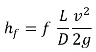
(Eqn. 1)
Where:
- hf= frictional head loss [m]
- f = friction factor (dimensionless)
- L = length of the pipe [m]
- D = internal diameter [m]
- v = flow velocity [m/s]
- g = gravitational acceleration [9.81 m/s²]
This formulation is primarily used for straight pipe sections, where f depends on the Reynolds number and pipe roughness.
Introducing Resistance Coefficients (K-Values)
While the Darcy-Weisbach equation is ideal for pipes, fittings and valves are better modeled using resistance coefficients, commonly denoted as K. This leads to a simplified expression for frictional head loss:
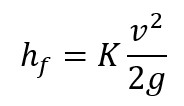
(Eqn. 2)
The resistance coefficient (K) is a dimensionless value specific to the component and flow conditions. This method is particularly useful because many manufacturers and handbooks publish standard K-values for common fittings, bends, valves, and other components.
Why Use K-Values?
- Vendor-specific data: Manufacturers often provide K-values or charts specific to their products.
- Simplicity: Once you know the velocity of the fluid, calculating the head loss is straightforward.
- Flexibility: Applicable to complex fittings where the Darcy equation is impractical.
Important Consideration from Crane’s Handbook
K-values are not always constant across sizes of the same component. While theoretically, resistance coefficients should remain constant for geometrically similar designs, real-world manufacturing limitations (e.g., structural strength, standards, and cost) often introduce variation.
So, it’s always best practice to:
- Consult vendor data specific to the fitting and size you’re using
- Use published estimates only as starting points for preliminary design
Unit Consistency in the Energy Balance
In energy balance equations, all terms—including frictional head loss—must have consistent units. Frictional head loss is typically expressed in meters. If needed, you can convert it to pressure using:
![]()
(Eqn. 3)
Where ρ is the fluid density in kg/m³.
Final Thoughts
Understanding and accurately accounting for frictional head loss is crucial when modeling pump and piping systems. Whether you're sizing a pump, analyzing system performance, or troubleshooting pressure losses, mastering the Darcy equation and resistance coefficient method will give you a powerful toolkit to tackle real-world engineering challenges.
Keep in mind that the resistance values you calculate are only estimates. It’s essential to include a reasonable buffer to account for uncertainties in these coefficients when sizing your pump. However, avoid the temptation to oversize the pump excessively—doing so can introduce new operational issues.
Want to learn how to strike the right balance? Explore the course Pump Sizing & Modeling Piping Systems For Liquids Course, where we go in-depth into friction factors, flow regimes, and building robust, real-world piping system models from scratch.
Receive Free Discounts!
Join our mailing list to receive the latest engineering blogs, tools, resources and discounts on courses.
Don't worry, your information will not be shared.
Author