Orifice Plate Sizing for Liquid Applications
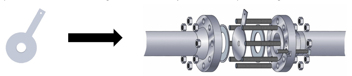
An orifice plate is a widely used device for measuring flow rate, reducing pressure, or restricting flow. When used to restrict flow or reduce pressure, it is often called a restriction plate. The orifice plate is a thin, machined plate with a precisely drilled hole known as the orifice bore. It is usually placed between two orifice flanges or more commonly, within an orifice plate housing.
How Orifice Plates Work
Orifice plates function similarly to valves by creating a restriction that adds resistance to flow in the piping system. The key design equation used for calculating the pressure drop across an orifice plate is quite similar to the valve flow coefficient equation, but with some important differences that we’ll explore.
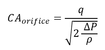
The following equation is used for orifice plate sizing:
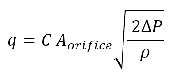
(Eqn.1)
Where:
- q: flow rate [m³/s]
- C: orifice flow coefficient [-]
- A: orifice area [m²]
- ΔP: pressure drop across the orifice [Pa]
- ρ: liquid density [kg/m³]
Orifice Flow Coefficient (C)
The orifice flow coefficient, also called the discharge coefficient (Cd), represents the frictional losses of the orifice plate. It’s typically determined empirically through experimental data. There are many formulas and charts that approximate the discharge coefficient based on parameters like orifice geometry, flow regime, and Reynolds number.
For example, Crane’s Technical Paper 410 provides charts showing the discharge coefficient for sharp-edged orifices at different Reynolds numbers and beta ratios. The beta ratio is defined as:
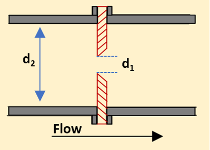
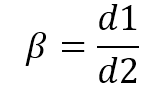
(Eqn.2)
Where:
- d₁: orifice bore diameter
- d₂: inlet pipe diameter
According to ISO 5167 and ASME MFC-3M, the recommended beta ratios range between 0.2 and 0.75. The discharge coefficient for sharp-edged orifice plates generally falls within the range of 0.6 to 0.8 as can be seen in the figure below.

Figure1: Discharge coefficient for sharp-edged orifice plates as a function of Reynolds number and beta ratio (Source: Crane Handbook)
Step 1: Gather System Information
Begin by determining the required flow rate and the pressure drop across the orifice plate. For example, if the orifice plate is positioned between a pressure regulator and an open tank, the pressure drop is calculated as the difference between the regulator's set point and the tank pressure.
If you have the flexibility to design the system, you can initially assume any reasonable value for the pressure drop. Once you have this value, proceed with calculations in Steps 2 to 4.
After completing these calculations, check the beta ratio (β). If the final beta ratio falls between 0.2 and 0.7, the pressure drop is considered acceptable. If β exceeds 0.7, increase the assumed pressure drop and recalculate. Conversely, if β is below 0.2, reduce the pressure drop.
For further insight into why it's important to maintain the beta ratio between 0.2 and 0.7, refer to the section below on practical considerations for beta ratio limits.
Step 2: Rearrange the Design Equation
Rearrange Equation 1 to isolate the known variables:
(Eqn.3)
Substitute the area A with the equation for the area of a circle:
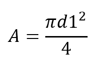
(Eqn.4)
Now, substitute this into Equation 3:
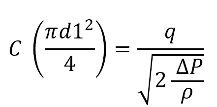
(Eqn.5)
At this stage, you can calculate the right-hand side of the equation, but you don’t yet know the flow coefficient C, which depends on the beta ratio, and therefore the orifice diameter, which you are trying to determine. You’ll need to guess and iterate.
Step 3: Make an Initial Guess for the Orifice Diameter
Start by making an initial guess for the orifice diameter d1d_1d1. Using this estimated diameter, calculate the beta ratio (β). Next, determine the Reynolds number based on the inlet pipe diameter d2d_2d2.
With both the beta ratio and Reynolds number, refer to a chart or table, such as those found in Crane’s Technical Paper 410 (see Figure 1), to find the flow coefficient (C).
Once you have the value of C, compute the left-hand side of Equation 5. Compare this result to the right-hand side of the equation:
- If the left-hand side is larger, make a note to reduce the diameter in your next iteration.
- If the left-hand side is smaller, increase the diameter estimate.
This iterative process will help refine your orifice diameter until both sides of the equation converge, leading to an optimal orifice plate size for your application.
Step 4: Iterate Until Convergence
Continue adjusting the guessed orifice diameter until both sides of Equation 5 converge, giving you the correct orifice size.
Practical Considerations for Beta Ratio Limits (0.2 to 0.7)
- Accuracy: The discharge coefficient is most stable and predictable for beta ratios between 0.2 and 0.7, ensuring accurate flow measurements.
- Pressure Drop: In practice, a balance is needed between achieving a measurable differential pressure (which increases with smaller orifices) and minimizing energy losses (which increase with higher pressure drops). The range of 0.2 to 0.7 ensures that the pressure drop is significant enough to measure accurately but not so high that it leads to excessive energy losses
- Industry Standards: ISO 5167 and ASME MFC-3M recommend staying within this range to ensure repeatable and reliable measurements. These standards also provide guidelines for upstream and downstream pipe lengths.
Conclusion
Orifice plate sizing is a crucial step in designing flow measurement systems for liquids. By understanding the relationship between pressure drop, flow rate, and the beta ratio, you can design systems that are both accurate and efficient. Always aim for a beta ratio between 0.2 and 0.7, and ensure that your system adheres to industry standards like ISO 5167 and ASME MFC-3M for best results.
For a deeper dive on pumps, check out the Pump Sizing & Modeling Piping Systems For Liquids Course
Receive Free Discounts!
Join our mailing list to receive the latest engineering blogs, tools, resources and discounts on courses.
Don't worry, your information will not be shared.
Author