Line Sizing Calculator Methodology Article
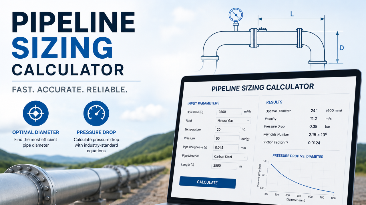
This calculator turns a single flow rate into a recommended pipe size. You enter the flow (and, optionally, the fluid properties), pick the service and the pipe material, and it returns the actual velocity, the smallest standard pipe that keeps that velocity inside the recommended range, and — when density and viscosity are supplied — the Reynolds number, flow regime, friction factor and pressure drop. This article documents exactly what each number is and where the method comes from.
On this page
The tool works in actual volumetric flow — m³/h for liquids and actual m³/h (Am³/h) for gases. If you enter a mass flow in kg/h it is converted to volume with the density. If your gas flow is at normal conditions (Nm³/h), convert it to actual conditions before entering it, because velocity depends on the gas state at the operating pressure and temperature.[4]
Density and viscosity are optional: with a volumetric flow the tool can compute velocity and suggest a size on the flow alone — the Reynolds number, regime and pressure drop simply remain blank until both properties are provided.
If you do not have a density on hand for a gas, the tool can compute it from the absolute pressure, temperature and molecular weight using the ideal gas law.[12]
P in Pa (absolute), M in kg/kmol, T in K. The ideal gas assumption weakens at high pressure or near the critical point — check those cases against real-gas data.
Velocity is the volumetric flow divided by the pipe's internal cross-sectional area.[4] The internal diameter comes from the standard pipe-dimension table for the selected material and schedule — ASME B36.10M for carbon steel,[13] ASME B36.19M for stainless steel,[14] and ASTM D1785 for PVC.[15]
v in m/s, Q in m³/h (hence the 3600), A in m², ID in m. This is the only calculation that does not need density or viscosity, which is why a volumetric-only run still returns a velocity and a size.
The tool steps through the standard sizes for the chosen material and schedule and recommends the smallest one whose velocity falls within the recommended range for the service. Velocity is the primary sizing criterion; the pressure drop in Step 6 is then reviewed against the system. The ranges below are guidelines, not hard limits — going outside them is acceptable when reviewed and judged suitable for the project.
Liquids are sized on velocity, with suction lines held to tighter limits to protect available NPSH.[1][2][3]
| Service | Velocity (m/s) | Basis |
|---|---|---|
| Pump suction | 1.2 – 2.1 | Crane TP-410 (4–7 ft/s) |
| Pump discharge / general service | 1.2 – 3.0 | Crane TP-410 (4–10 ft/s) |
| Boiler feed water | 2.4 – 4.6 | Crane TP-410 (8–15 ft/s) |
Gas velocity limits exist mainly to control noise and pipe vibration. The tool offers several published bases:
| Basis | Max velocity | Note |
|---|---|---|
| Onshore rule of thumb | ≤ 30 m/s | Common upper bound for dry process gas[2] |
| API RP 14E | ≤ 18 m/s (60 ft/s) | Conservative; common offshore[9] |
| NORSOK P-001 | density-based, cap 60 m/s | Accounts for gas density[10] |
| Saturated steam | 20 – 50 m/s | Velocity-method sizing[11] |
| Superheated steam | 50 – 70 m/s | Dry gas; no moisture erosion[11] |
The NORSOK option uses a density-dependent limit — a denser gas requires a lower velocity to stay within acceptable noise levels:
ρ = gas density in kg/m³, V in m/s. Because this limit needs density, the NORSOK basis requires a density input (directly or via the ideal gas option).
With density and viscosity available, the tool computes the Reynolds number to classify the flow and to feed the friction factor.[5] It treats Re below 2 300 as laminar and above as turbulent.
ρ in kg/m³, v in m/s, D = internal diameter, μ = dynamic viscosity. Without ρ and μ this step is skipped and the result is reported as velocity-only.
The Darcy friction factor depends on the regime and the relative roughness, ε/D (with absolute roughness taken from the selected material). In laminar flow it is exact; in turbulent flow the tool uses explicit correlations so no iteration is needed.
An explicit approximation to the Colebrook–White equation.[7]
For gas lines the tool uses the Chen explicit correlation, another accurate non-iterative solution of the Colebrook–White relationship.[8]
The pressure drop uses the Darcy–Weisbach equation, reported per 100 m of straight pipe (fittings and valves are not included).[6] For liquids this is informational: size on velocity first, then confirm the drop is workable for the available pump head and step up a size if it is too high.
L = 100 m basis, D = internal diameter. Result converted to bar per 100 m.
Water at 20 °C (ρ = 998.2 kg/m³, μ = 1.002 cP), 50 m³/h, on a pump suction line (1.2–2.1 m/s), carbon steel, Schedule 40.
Stepping up the standard sizes, the velocity falls into the allowable band at NPS 4":
| Size (Sch 40) | Internal diameter | Velocity | Verdict |
|---|---|---|---|
| NPS 3" | 77.92 mm | 2.91 m/s | above 2.1 — too fast |
| NPS 4" | 102.26 mm | 1.691 m/s | within band — selected |
For the selected NPS 4" Schedule 40 line:
| Volumetric flow | 50 m³/h |
| Actual velocity | 1.691 m/s |
| Reynolds number | 172 275 |
| Flow regime | Turbulent |
| Relative roughness ε/D | 0.00044 |
| Friction factor (Darcy) | 0.0189 |
| Pressure drop | 0.2637 bar / 100 m |
These figures match the live calculator's output for the same inputs.
- The tool sizes on velocity; pressure drop is reported for review, not enforced as a limit.
- Pressure drop covers straight pipe only (per 100 m) — fittings, valves, and elevation are not included.
- Velocity ranges are guidelines; project design basis and company standards take precedence.
- Gas pressure drop and velocity are single-point values; for compressible flow with significant ΔP, confirm with hydraulic software.
- The ideal gas option assumes ideal behaviour; verify for high-pressure or near-critical gases.
- With density and viscosity omitted, only velocity and the size suggestion are produced.
- Internal diameters follow the published pipe schedule for the selected material (e.g. ASME B36.10M for carbon steel).
- Crane Co. — Flow of Fluids Through Valves, Fittings, and Pipe, Technical Paper No. 410 (TP-410).
- Engineering ToolBox — Pipe Line Velocities vs. Fluid (typical liquid, gas and vapour velocities).
- Engineering ToolBox — Water Systems — Maximum Flow Velocities.
- Engineering ToolBox — Pipe Velocity and Volume Flow.
- Engineering ToolBox — Reynolds Number.
- Engineering ToolBox — Darcy–Weisbach Equation.
- Swamee, P.K. & Jain, A.K. (1976). Explicit equations for pipe-flow problems. Journal of the Hydraulics Division, ASCE, 102(5), 657–664.
- Chen, N.H. (1979). An explicit equation for friction factor in pipe. Industrial & Engineering Chemistry Fundamentals, 18(3), 296–297.
- American Petroleum Institute — API RP 14E, Design and Installation of Offshore Production Platform Piping Systems.
- Standards Norway — NORSOK P-001, Process Design, Edition 5 (2006).
- Spirax Sarco — Pipes and Pipe Sizing (steam velocity guidance).
- Engineering ToolBox — The Ideal Gas Law (gas density).
- ASME B36.10M — Welded and Seamless Wrought Steel Pipe (carbon steel schedules and internal diameters). Freely accessible chart: Engineering ToolBox — Steel Pipes Dimensions (ASME B36.10/B36.19).
- ASME B36.19M — Stainless Steel Pipe (stainless schedules 5S–160S and internal diameters); tabulated alongside B36.10M in the Engineering ToolBox chart above.[13]
- ASTM D1785 — Standard Specification for Poly(Vinyl Chloride) (PVC) Plastic Pipe, Schedules 40, 80, and 120 (PVC internal diameters).
Estimates for preliminary engineering and screening. Confirm final selection with vendor data and a detailed hydraulic analysis. Not a substitute for review by a qualified engineer.
Receive Free Discounts!
Join our mailing list to receive the latest engineering blogs, tools, resources and discounts on courses.
Don't worry, your information will not be shared.
Author